4. Prerequisite Hardware Setup
4.1. Setting up the Deployer Node
It is recommended that the deployer node have at least one available core of a XEON class processor, 16 GB of memory free and 64 GB available disk space. When using the POWER-Up software installation capabilities, it is recommended that 100 GB of disk space be available and that there be at least 40 GB of free disk space in the partition holding the /srv directory. For larger clusters, additional cores, memory and disk space are recommended. A 4 core XEON class processor with 32 GB memory and 320 GB disk space is generally adequate for clusters up to several racks.
The deployer node requires internet access for setup and installation of the POWER-UP software and may need internet access for creation of any repositories needed for software installation. This can be achieved through the interface used for connection to the management switch (assuming the management switch has a connection to the internet) or through another interface. Internet access requirements for software installation depends on the software installation module. Internet access is required when running cluster deployments.
4.1.1. Operating Sytem and Package setup of the Deployer Node
- Deployer OS Requirements:
- Ubuntu (Software installation is not yet supported under Ubuntu)
- Release 14.04LTS or 16.04LTS
- sudo privileges
- RHEL (Software installation is supported with POWER-Up vs 2.1. Cluster deployment is not yet supported under RHEL)
- Release 7.2 or later
- Extra Packages for Enterprise Linux (EPEL) repository enabled (https://fedoraproject.org/wiki/EPEL)
- sudo privileges
- Enable Red Hat ‘optional’ and ‘extra’ repository channels or enable the repository on the RHEL installation iso if available. (https://access.redhat.com/solutions/1355683) (required only if using the POWER-Up software installer)
- Power8:
- $ sudo subscription-manager repos –enable=rhel-7-for-power-le-optional-rpms
- $ sudo subscription-manager repos –enable=rhel-7-for-power-le-extras-rpms
- Power9:
- $ sudo subscription-manager repos –enable=rhel-7-for-power-9-optional-rpms
- $ sudo subscription-manager repos –enable=rhel-7-for-power-9-extras-rpms
- Optional:
- Assign a static, public ip address to the BMC port to allow external control of the deployer node.
- Enable ssh login
4.1.2. Network Configuration of the Deployer Node
For Software Installation
Use of the POWER-Up software installer requires that an interface on the installer node be pre-configured with access to the cluster nodes. If the cluster was not deployed by POWER-Up, this needs to be done manually. If the cluster has been deployed by POWER-Up, the PXE network will be automatically configured and can be used for software installation.
Although a routed connection to the cluster can be used for software installs, It is preferable that the interface used have an IP address in the subnet of the cluster network to be used for installation.
For Bare Metal Deployments
For bare metal deployments the deployer port connected to the management switch must be defined in /etc/network/interfaces (Ubuntu) or the ifcfg-eth# file (RedHat). e.g.:
auto eth0      # example device name
iface eth0 inet manual
POWER-Up can set up a subnet and optionally a vlan for it’s access to the switches in the cluster. It is recommended that the deployer be provided with a direct connection to the management switch to simplify the overall setup. If this is not possible, the end user must insure that tagged vlan packets can be communicated between the deployer and the switches in the cluster. The interface used for PXE and IPMI can have additional IP addresses on it, but they should not be in the PXE or IPMI subnet. Similarly, this interface can have existing tagged vlans configured on it, but they should not be the vlans to be used by the PXE and IPMI networks.
An example of the config file parameters used to configure initial access to the switches is given above with POWER-Up setup of the switch management network. For a detailed description of these keys see deployer ‘mgmt’ networks, ‘switches: mgmt:’ and ‘switches: data:’ in the Cluster Configuration File Specification.
4.2. Hardware initialization
Insure the cluster is cabled according to build instructions and that a list of all switch port to node physical interface connections is available and verified. Note that every node must have a physical connection from both BMC and PXE ports to a management switch. (see the example cluster in Appendix-D)
Cable the deployer node directly to a management switch. For large cluster deployments, a 10 Gb connection is recommended. The deployer node must have access to the public internet (or site) network for retrieving software and operating system image files. If the cluster management network does not have external access an alternate connection must be provided, such as the cluster data network.
Insure that the BMC ports of all cluster nodes are configured to obtain an IP address via DHCP.
If this is a first time OS install, insure that all PXE ports are configured to obtain an IP address via DHCP. On OpenPOWER servers this is typically done using the Petitboot menus, e.g.:
Petitboot System Configuration
──────────────────────────────────────────────────────────────────────────────
 Boot Order     (0) Any Network device
                (1) Any Device:

                [    Add Device:     ]
                [  Clear & Boot Any  ]
                [       Clear        ]

 Timeout:       10    seconds


 Network:       (*) DHCP on all active interfaces
                ( ) DHCP on a specific interface
                ( ) Static IP configuration
Acquire any needed public and or site network addresses.
Insure you have a config.yml file to drive the cluster configuration. If necessary, edit / create the config.yml file (see section Creating the Config File)
Configuring the Cluster Switches
POWER-Up can configure supported switch models (See Supported Hardware). If automated switch configuration is not desired ‘passive’ switch mode can be used with any switch model (See Preparing for Passive Mode)
Initial configuration of cluster switch(es)
In order to configure your cluster switches, Cluster POWER-Up needs management access to all your cluster switches. This management network can be vlan isolated but for most applications a non-isolated management network is suitable and simpler to setup. To prepare for a non-isolated management network, you need to create management interfaces on all your cluster switches. The IP addresses for these management interfaces all need to be in the same subnet. The deployer will also need an IP address in this subnet. You will also need to know a userid and password for each switch and each switch will need to be enabled for SSH access. One of the management switches in your cluster must have a data port accessible to the deployer. This can be a routed connection supporting tagged vlans, but it is recommended that there be a direct connection between the deployer and one management switch.
For out of box installation, it is usually easiest to configure switches using a serial connection. Alternately, if the switch has a connection to a network without a DHCP server running, you may be able to access the switch at a default IP address. If the switch has a connection to a network with a DHCP server running, you may be able to reach it at the assigned IP address. See the switches installation guide. For additional info on Lenovo G8052 specific commands, see Appendix-G and the Lenovo RackSwitch G8052 Installation guide).
POWER-Up setup of the switch management network
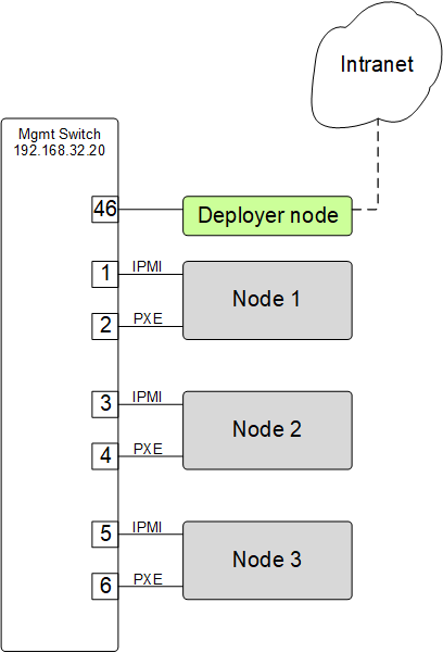
In this simple cluster example, the management switch has an in-band management interface. The initial setup requires a management interface on all switches configured to be accessible by the deployer node. The configured ip address must be provided in the ‘interfaces:’ list within each ‘switches: mgmt:’ and ‘switches: data:’ item. Cluster POWER-Up uses this address along with the provided userid and password credentials to access the management switch. Any additional switch ‘interfaces’ will be configured automatically along with deployer ‘mgmt’ networks.
The following snippets are example config.yml entries for the diagram above:
Switch config file definition:
switches:
    mgmt:
        - label: mgmt_switch
          userid: admin
          password: abc123
          class: lenovo
          interfaces:
              - type: inband
                ipaddr: 192.168.32.20
          links:
              - target: deployer
                ports: 46
Deployer ‘mgmt’ networks:
deployer:
    networks:
        mgmt:
            - device: enp1s0f0
              interface_ipaddr: 192.168.32.95
              netmask: 255.255.255.0
Note that the deployer mgmt interface_ipaddress is in the same subnet as the management switches ipaddr. (192.168.32.0 netmask: 255.255.255.0)
As an example, management switch setup commands for the Lenovo G8052 are given below. For other supported switches consult the switch documentation.
Enable configuration of the management switch:
enable
configure terminal
Enable IP interface mode for the management interface:
RS G8052(config)# interface ip 1
assign a static ip address, netmask and gateway address to the management interface. This must match one of the switch ‘interfaces’ items specified in the config.yml ‘switches: mgmt:’ list:
RS G8052(config-ip-if)# ip address 192.168.32.20  # example IP address
RS G8052(config-ip-if)# ip netmask 255.255.255.0
RS G8052(config-ip-if)# vlan 1  # default vlan 1 if not specified
RS G8052(config-ip-if)# enable
RS G8052(config-ip-if)# exit
admin password. This must match the password specified in the config.yml corresponding ‘switches: mgmt:’ list item. The following command is interactive:
access user administrator-password
disable spanning tree:
spanning-tree mode disable
enable secure https and SSH login:
ssh enable
ssh generate-host-key
access https enable
Save the config. For additional information, consult vendor documentation):
copy running-config startup-config
Adding additional management and data switch(es)
For out of box installation, it is usually necessary to configure the switch using a serial connection. See the switch installation guide. As an example, for Mellanox switches, a configuration wizard can be used for initial configuration:
assign hostname
set DHCP to no for management interfaces
set zeroconf on mgmt0 interface: to no
do not enable ipv6 on management interfaces
assign static ip address. This must match the corresponding interface ‘ipaddr’ specified in the config.yml file ‘switches: data:’ list, and be in a deployer ‘mgmt’ network.
assign netmask. This must match the netmask of the deployer ‘mgmt’ network that will be used to access the management port of the switch.
default gateway
Primary DNS server
Domain name
Set Enable ipv6 to no
admin password. This must match the password specified in the config.yml corresponding ‘switches: data:’ list item.
disable spanning tree. Typical industry standard commands:
enable
configure terminal
no spanning-tree
enable SSH login:
ssh server enable
Save config. In switch config mode:
configuration write
If using redundant data switches with MLAG or vPC, connect only a single inter switch peer link (IPL) between switches or leave the IPL links disconnected until Cluster POWER-Up completes. (This avoids loops)
Add the additional switches to the config.yml. A data switch is added as shown below:
Switch config file definition:
switches:
    .
    .
    data:
        - label: data_switch
          userid: admin
          password: abc123
          class: cisco
          interfaces:
              - type: inband
                ipaddr: 192.168.32.25
          links:
              - target: mgmt_switch
                ports: mgmt
This completes normal POWER-Up initial configuration. For additional information and examples on preparing cluster hardware, see the sample configurations in the appendices.
Preparing for Passive Mode
In passive mode, POWER-Up configures the cluster compute nodes without requiring any management communication with the cluster switches. This facilitates the use of POWER-Up even when the switch hardware is not supported or in cases where the end user does not allow 3rd party access to their switches. When running POWER-Up in passive mode, the user is responsible for configuring the cluster switches. The user must also provide the Cluster POWER-Up software with MAC address tables collected from the cluster switches during the POWER-Up process. For passive mode, the cluster management switch must be fully programmed before beginning cluster POWER-Up, while the data switch should be configured after POWER-Up runs.
Configuring the management switch(es)
- The port(s) connected to the deployer node must be put in trunk mode with allowed vlans associated with each respective device as defined in the deployer ‘mgmt’ and ‘client’ networks.
- The ports on the management switch which connect to cluster node BMC ports or PXE interfaces must be in access mode and have their PVID (Native VLAN) set to the respective ‘type: ipmi’ and ‘type: pxe’ ‘vlan’ values set in the ‘deployer client networks’.
Configuring the data switch(es)
Configuration of the data switches is dependent on the user requirements. The user / installer is responsible for all configuration. Generally, configuration of the data switches should occur after Cluster POWER-Up completes. In particular, note that it is not usually possible to acquire complete MAC address information once vPC (AKA MLAG or VLAG) has been configured on the data switches.