15. Multiple Tenant Support
POWER-Up has the ability to segment a physical cluster into multiple isolated groups of nodes, allowing multiple users / tenants to use the cluster at the same time while maintaining complete isolation between tenants.
The process of sub-dividing a cluster into multiple groups is simple. You create a config.yml file for each group of nodes and deploy the groups one at a time. Each group must have a unique PXE and IPMI subnet and vlan number. The mgmt network can be common for all groups. POWER-Up creates a container and isolated networks on the deployer for each tenant in the cluster. A symbolic link to the inventory.yml file for each group is created in the power-up directory with the name inventoryn.yml where n is the number of the pxe vlan for the group.
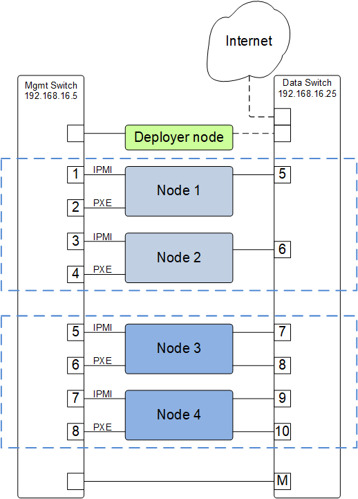
POWER-Up Support for multiple tenants
As an example, the figure above shows a basic cluster with four nodes. To configure these into two groups of two nodes, create a config file for each group. Edit the deployer section of each config file and under the client subsection, specify a unique container_ipaddr, bridge_ipaddr and vlan for the ipmi and pxe networks for each group of nodes.
For example, the two groups could be configured as below;
Group 1:
deployer:
    networks:
        mgmt:
            - device: enP10p1s0f0
              interface_ipaddr: 192.168.16.3
              netmask: 255.255.255.0
        client:
            - device: enP10p1s0f0
              type: ipmi
              container_ipaddr: 192.168.30.2
              bridge_ipaddr: 192.168.30.3
              netmask: 255.255.255.0
              vlan: 30
            - device: enP10p1s0f0
              type: pxe
              container_ipaddr: 192.168.40.2
              bridge_ipaddr: 192.168.40.3
              netmask: 255.255.255.0
              vlan: 40
Group 2:
deployer:
    networks:
        mgmt:
            - device: enP10p1s0f0
              interface_ipaddr: 192.168.16.3
              netmask: 255.255.255.0
        client:
            - device: enP10p1s0f0
              type: ipmi
              container_ipaddr: 192.168.31.2
              bridge_ipaddr: 192.168.31.3
              netmask: 255.255.255.0
              vlan: 31
            - device: enP10p1s0f0
              type: pxe
              container_ipaddr: 192.168.41.2
              bridge_ipaddr: 192.168.41.3
              netmask: 255.255.255.0
              vlan: 41
Next, edit the switch ports list in the node_templates section of each config file;
Group 1:
node_templates:
    - label: ubuntu1604-node
      ipmi:
          userid: ADMIN
          password: admin
      os:
          profile: ubuntu-16.04-server-ppc64el
          users:
              - name: user1
                password: $6$Utk.IILMG9.$EepS/sIgD4aA.qYQ3voZL9yI3/5Q4vv.p2s4sSmfCLAJlLAuaEmXDizDaBmJYGqHpobwpU2l4rJW.uUY4WNyv.
                groups: sudo
          install_device: /dev/sdj
      physical_interfaces:
          ipmi:
              - switch: mgmt1
                ports:
                    - 1
                    - 3
          pxe:
              - switch: mgmt1
                interface: pxe-ifc
                rename: true
                ports:
                    - 2
                    - 4
          data:
              - switch: data1
                interface: static_1
                rename: true
                ports:
                    - 5
                    - 6
Group 2:
node_templates:
    - label: ubuntu1604-node
      ipmi:
          userid: ADMIN
          password: admin
      os:
          profile: ubuntu-16.04-server-ppc64el
          users:
              - name: user1
                password: $6$Utk.IILMG9.$EepS/sIgD4aA.qYQ3voZL9yI3/5Q4vv.p2s4sSmfCLAJlLAuaEmXDizDaBmJYGqHpobwpU2l4rJW.uUY4WNyv.
                groups: sudo
          install_device: /dev/sdj
      physical_interfaces:
          ipmi:
              - switch: mgmt1
                ports:
                    - 5
                    - 7
          pxe:
              - switch: mgmt1
                interface: pxe-ifc
                rename: true
                ports:
                    - 6
                    - 8
          data:
              - switch: data1
                interface: static_1
                rename: true
                ports:
                    - 7
                    - 9
          data:
              - switch: data1
                interface: static_2
                rename: true
                ports:
                    - 8
                    - 10
For a complete config file for a basic cluster, See Appendix-D
Assuming your two config files are named config-T1.yml and config.T2.yml and residing in the power-up directory, to deploy the two groups:
pup deploy config-T1.yml
After the first deploy completes:
pup deploy config-T2.yml
Note
POWER-Up does not currently support the execution of two deploys at the same time. When deploying multiple groups of nodes, the groups must be deployed sequentially.
Note that if you move a node from an already deployed group to a new group, it can take up to one hour for it’s IPMI IP lease to expire. If the node is moved to a new subnet before the lease expires you will not be able to access the nodes IPMI system until it renews it’s IP lease in the new subnet. To avoid this, you can manually cycle power to the node. Alternately, you can use the ipmitool to reset the BMC of the node to be moved:
ipmitool -I lanplus -H 192.168.30.21 -U ADMIN -P admin mc reset cold
then immediately run:
pup config --mgmt-switches new-group-config.yml